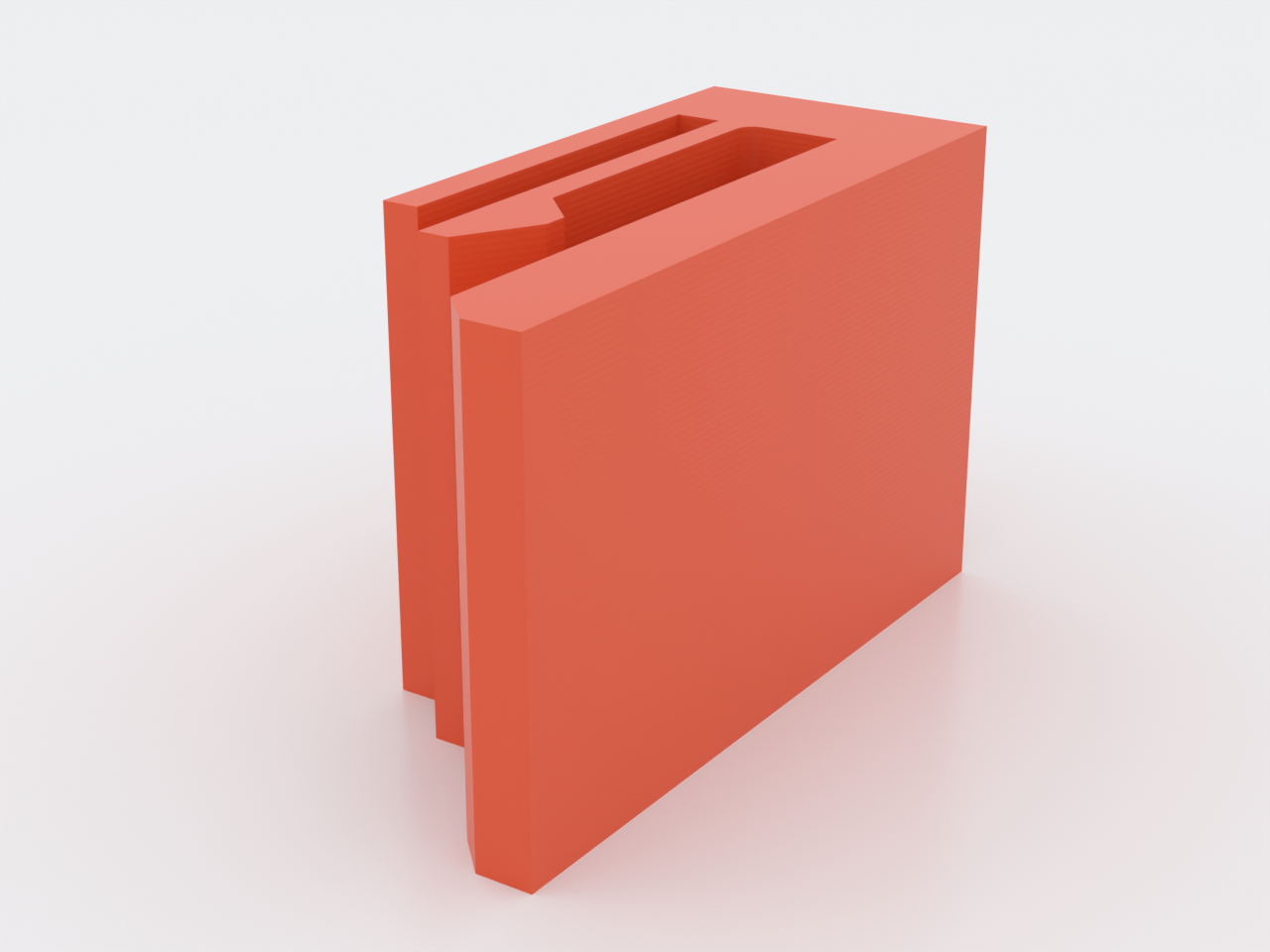
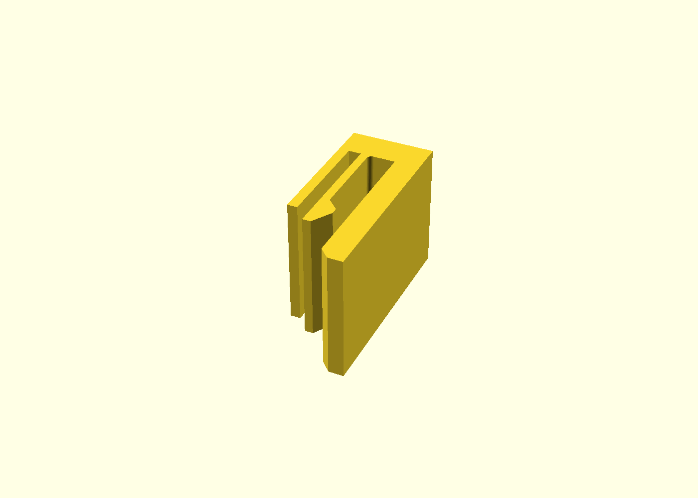
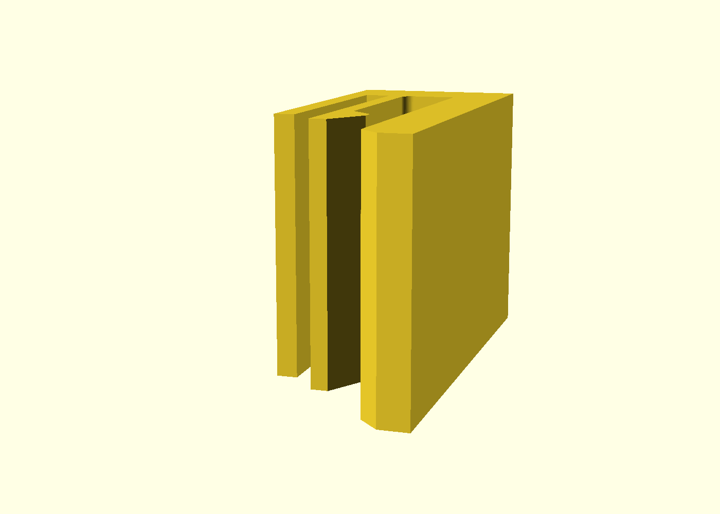



A one-piece clip that snaps onto the edge of a 3 mm plate — shelf stock,
acrylic, MDF, cardboard — and holds by cantilever deflection: the
canonical snap-fit, built as the reference design for the repo's compliant-
mechanics catalog (docs/advanced-techniques.md, Domain 1). Push it on, a
finger cams open over the plate, springs back behind it, and the clip grips
by spring preload; pulling it off takes about twice the force, via the steep
retention shoulder. Every dimension comes from the small-length-flexural-
pivot relations — not guessed: stiffness K = E·I/L, insertion force
F = 3EIδ/L³ ≈ 5 N, root stress bounded at 25 MPa (≈ half of PETG's yield).
What you get
snap-cantilever-clip— one part, ≈ 10 × 24 × 15 mm, ≈ 2.6 g. No hardware, no tools: it clips on and pulls off by hand.
How it works
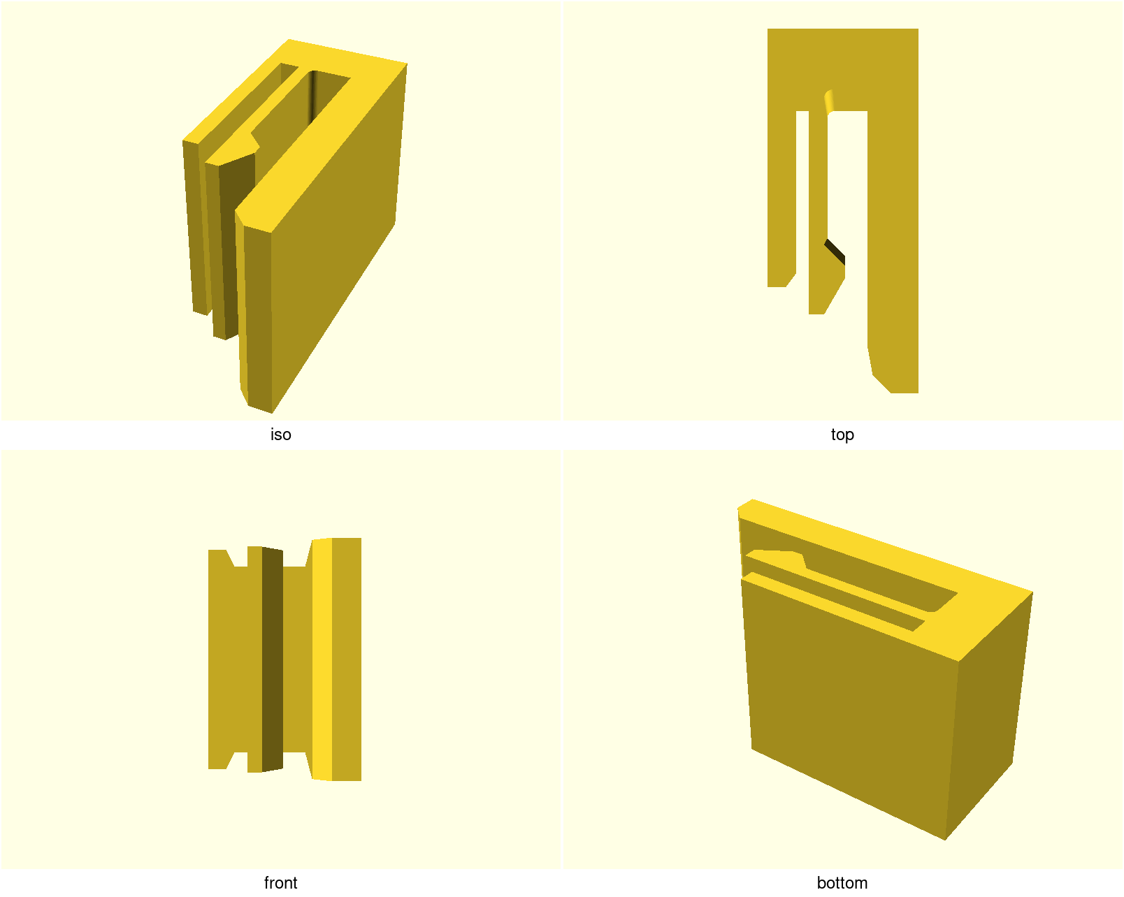
The clip is a channel one jaw of which is a cantilever finger carrying a lip (a shallow 30° lead-in ramp ahead, a blunt apex, a steep 45° shoulder behind). Pushing the clip onto the plate edge rides the ramp — the finger deflects 1.2 mm — then springs back onto the plate face, preloading it against the stiff jaw. That preload is the grip. A guard rail stands at the finger's overtravel limit, so an over-hard push bottoms out on plastic instead of folding the flexure to failure.
| Preview | What it shows |
|---|---|
 | The bed-plane working drawing: channel, lip tooth with both cam angles, guard gap, root fillet |
 | The throat the plate passes, lead-in funnel, lip tooth dead centre |
 | The flexure root from the guard side: guard rail, relief slot, finger and strap converging |
 | Close cut over the strap: the slot and channel terminating against it, the root-fillet arc on the channel corner |
Print settings
- Material: PETG (the design datum) or PP for far more cycles. Do not print the flexure in PLA — it work-hardens and cracks. PETG prints the channel a hair tight and may leave a couple of strings in the guard slot — flick them out with a blade tip. PP earns its extra cycles but is a warp monster on a part this small — brim, slow first layer, and expect tuning; PETG stays the sane default.
- Layer height: 0.2 mm — a requirement for this part, not a suggestion: the finger is a 1 mm free-standing wall and its layer faces are the fatigue-critical surface.
- Initial layer horizontal expansion: −0.2 mm — first-layer squish
(elephant foot) eats the channel's 0.1 mm/side working clearance; this
free slicer setting is the first fix for a tight channel, before reaching
for
plate_tol(it also keeps the flexure numbers untouched). - Infill: 20 % — the walls and perimeters do the work; the body is solid where it matters
- Supports: none — every wall is vertical, the whole silhouette lands on the bed at once
- Seam: set Back (or scarf) — the perimeter loop is short and a default aligned seam can stack its ridge on the lip tooth or a channel wall
- Orientation: flat, as modelled — load-bearing. The silhouette is authored in the bed plane so the finger bends within a layer. Print it upright and the finger delaminates on the first insertion.
Print this first
The clip is already coupon-sized, so the part is the coupon
(snap-cantilever-clip-coupon.scad, ~16 min): print it, snap it onto a
3 mm card edge, and feel the insertion before committing to changes.
Tune in this order:
t— stiffness scales witht³; it is the whole knob. Too hard to push → lower it; sloppy retention → raise it.root_fillet— keep ≥ 0.5·t(asserted): the root is where a flexure cracks.grip_p— only aftertis settled (it sets both deflection and preload).plate_tol— the fit, not the spring: if the plate binds or won't seat in PETG, 0.2 → 0.3 mm before touching the flexure parameters.
Snap the printed coupon 20× and inspect the root: any whitening line or
creep set there means stop, raise t or root_fillet, requalify.
Parameters
| Parameter | Default | What it does |
|---|---|---|
plate_t | 3.0 mm | plate thickness to grip — the channel is built from it |
plate_tol | 0.2 mm | slide clearance in the channel — the fit knob (see above) |
plate_depth | 20 mm | how deep the plate seats into the channel |
t | 1.0 mm | flexure thickness — the highest-leverage knob (K ∝ t³) |
L | 12 mm | root-to-lip beam length — longer lowers stress at the same rotation |
w | 15 mm | clip width = beam width; insertion force scales with it |
grip_p | 1.4 mm | lip protrusion — the snap interference (sets deflection and preload) |
root_fillet | 0.6 mm | flexure root radius; must stay ≥ 0.5·t (fatigue rule, asserted) |
ramp_deg | 30° | lead-in cam angle — the insertion force multiplier |
shoulder_deg | 45° | retention cam; 45° ≈ removable at ~2× insertion, 90° = non-releasing |
E | 2000 MPa | PETG modulus datum behind the echoed force/stress predictions |
All parameters are at the top of snap-cantilever-clip.scad, grouped in
Customizer sections; override with -D 'plate_t=2.5'. The predicted
K, insertion force and root stress for the current values are echoed at
render time — see NOTES.md for the full derivation, the guard-rail rule and
the fatigue caveat (cycle target deliberately undecided; qualify on the
coupon).