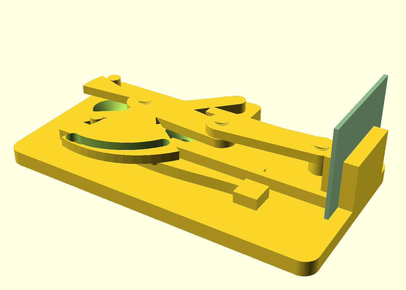
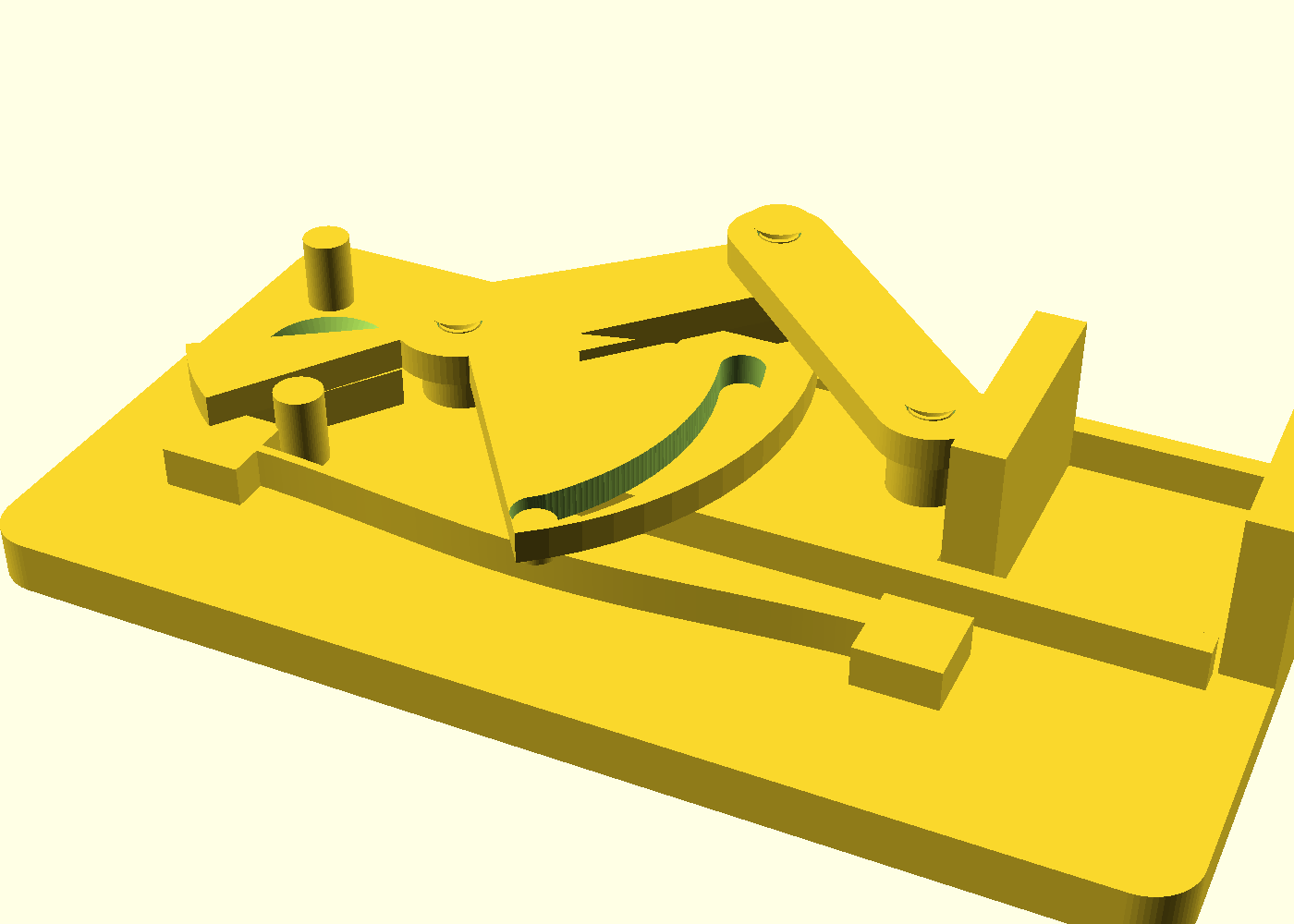
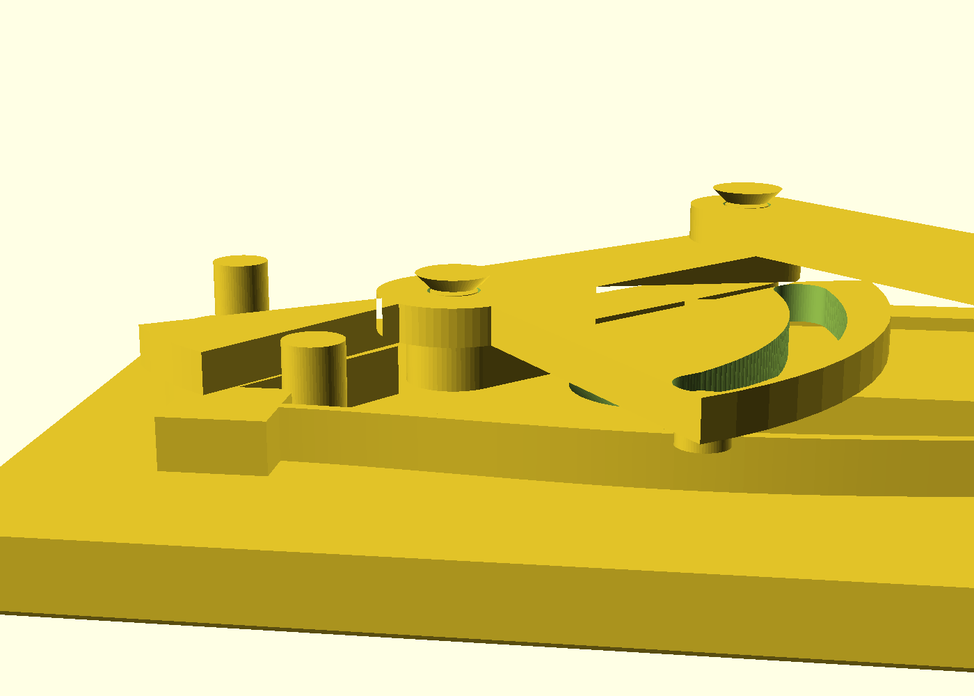
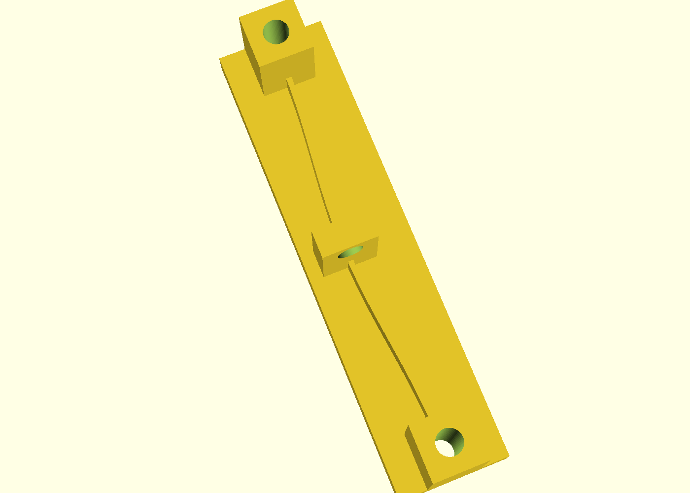
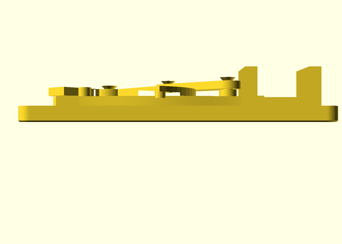
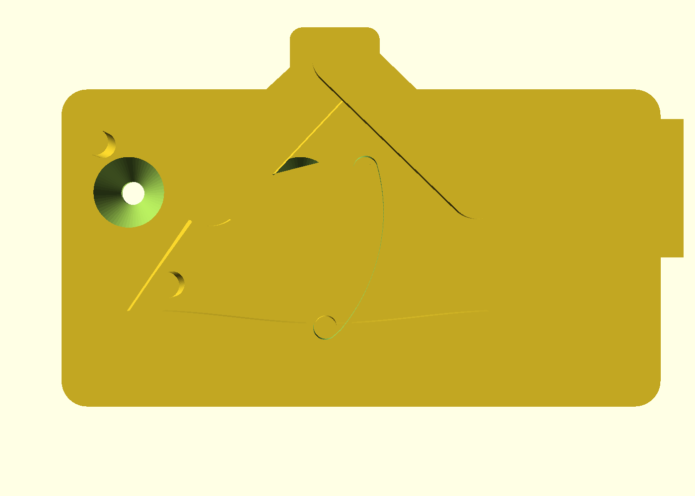
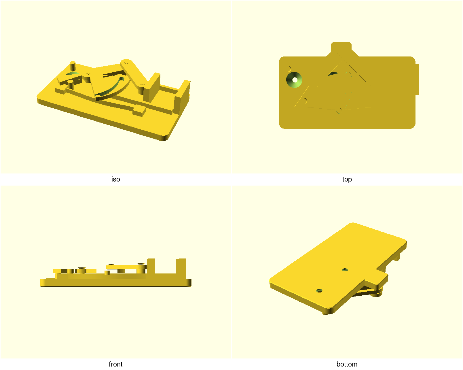
A print-in-place toggle clamp for bench-top workholding: squeeze the lever, the jaw closes on your workpiece, the linkage crosses dead center and seats on a hard stop — for stock in the locked band the workpiece's own reaction then torques the lever into that stop, not out of it — and a buckled-beam arch gives the toggle a positive snap in both directions. One PETG print, four moving parts, zero assembly hardware, no supports.
What "self-locking" honestly means here. A fixed linkage locks a band
of thickness, not a whole range. Out of the box the over-center lock engages
for stock about 1.4–1.6 mm thick (a 1.6 mm PCB is the design target);
from there up to ~6 mm the arch spring holds the jaw closed — fine for a
soldering or filing session, but PETG creeps, so don't trust a spring-held
glue-up overnight; above ~6 mm the lever will not stay closed, and below
~0.8 mm (the dead-center gap) the jaws cannot touch the work at all. Other
stock is a parameter change, not a redesign: set dead_center_gap ≈ your
thickness − 0.5 mm and reprint — the [over-center] echo lines print the
locked band for whatever numbers you set. In practice most people tune for
the one or two thicknesses they really clamp and leave it there — and
because a retuned clamp is visually identical to a default one, mark the
paddle with paint pen the day you retune.
The feel is the tell: a hard seat into the stop means the locked band
(vibration-proof — file away; by geometry, pending the field test); a
springy settle means the arch is holding
(fine for a soldering session, not overnight). Mind FR4's tolerance here:
it commonly runs ±10 % on thickness, and the locked band ends at 1.6 mm —
so a fat-but-nominal 1.6 mm board lands arch-held, not locked. "Sized for
1.6 mm PCB" is a strong default, not a promise; the retune knob is
dead_center_gap.
What you get
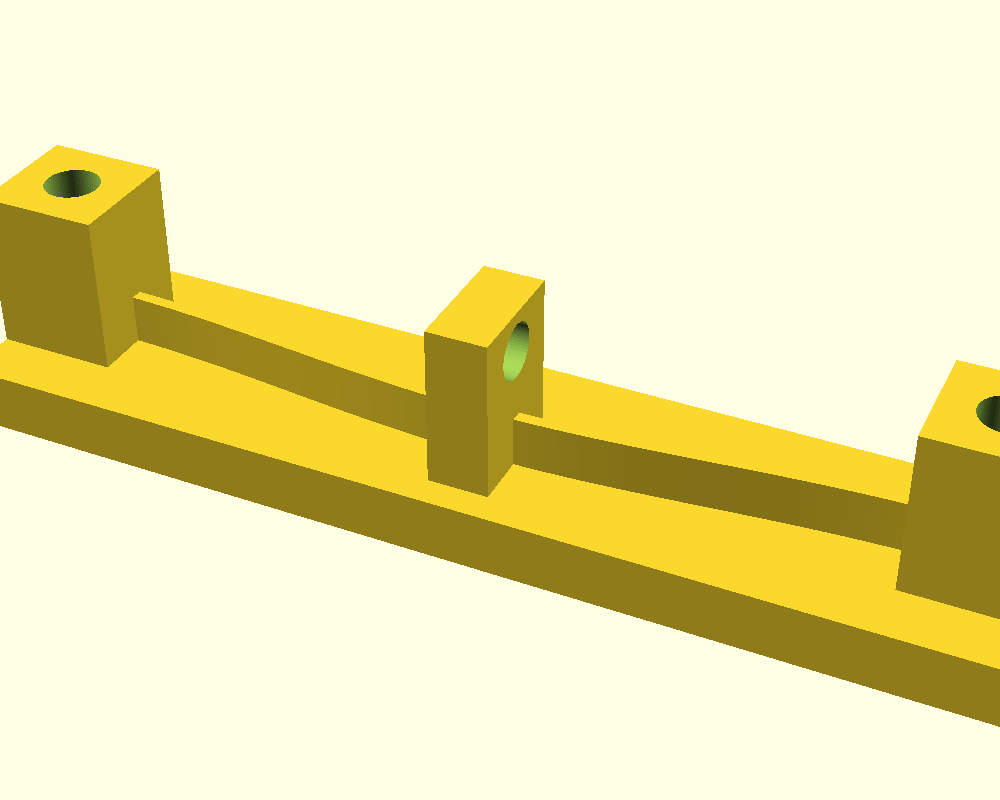
over-center-toggle-clamp— the clamp, ~140 × 89 × 27 mm (the handle sweep sets the width; a plate tab rides under the printed-pose crank eye). Jaws open to 25 mm, faces 30 mm deep and 20 mm tall; grips per the bands above; mounts with two M5 screws at 40 mm centres.over-center-toggle-clamp-coupon— print this first: the same production flexure in a test frame, ~103 × 24 × 22 mm, and the force-measuring artifact (see below).
Print settings
- Material: PETG (PP works; do not use PLA — the flexure fatigues)
- Layer height: 0.2 mm (the Z clearances are two layers; coarser layers change the fit)
- Infill: 25 %, 3 perimeters
- Seam: scarf or random — never aligned: a stacked seam on the arch's tensile face is a fatigue notch, and an aligned seam can eat a 0.25 mm pivot film
- Bridges: 100 % bridge cooling. The ~40 mm link span sags by design into a 4.8 mm clearance — a hairy underside there is cosmetic. Textured PEI is kinder to the big first layer than smooth sheets. If the link feels stiff out of the printer, don't force the handle — flip the part and inspect the link's underside first; a welded bridge is a reprint, not a flex.
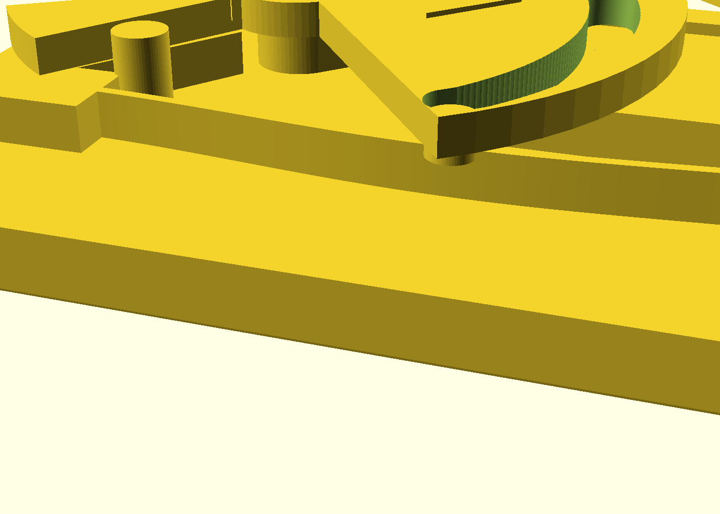
- Supports: none — everything prints flat as rendered; the moving parts ride 0.4 mm films (the lever band prints its first layer as a film over sacrificial shelves, the rail tops and the arch). The film edges and undersides are meant to look rough — that roughness is what keeps the parts free. Never support them.
- Orientation: exactly as rendered (plate down, lever open) — the flexure must bend across printed roads, which the flat pose guarantees
- Before the real print: run the coupon. It proves two things — your arch's snap force (hang ~1.1 kg on the tab) and your flow calibration. It contains no films, so it does not prove the clamp's joints print free; the fuse gate proves that for the design geometry, and your coupon-proven calibration covers the rest. A dead clamp costs ~5 h and ~61 g of PETG; the coupon costs ~1 h 45 m and ~16 g — about a third of the time and a quarter of the filament to know your snap and flow before you bet the evening.
Parameters
| Parameter | Default | What it does |
|---|---|---|
jaw_gap_max | 25 mm | Jaw opening at the printed pose |
jaw_depth | 30 mm | Gripping depth of the jaw faces |
jaw_height | 20 mm | Jaw face height above the base plate |
dead_center_gap | 0.8 mm | Jaw gap left at dead center — the locked-band knob: locked thickness ≈ this + 0.5 mm |
theta_closed | −6° | Closed-seat angle, negative = past dead center (the locked side; the render refuses a positive value) |
arch_rise | 3 mm | Arch rise — the snap-strength knob (with arch_t) |
arch_t | 1.2 mm | Flexure thickness; ≥ 1.2 mm (3 perimeters) |
E_mod | 2000 MPa | PETG modulus; set 1500 for PP. Tune from the coupon |
k_struct | 200 N/mm | Estimated clamping-loop stiffness — sizes the echoed locked band, never the geometry |
pip_xy / pip_z | 0.25 / 0.4 mm | Sliding film / layer-snapped film — raise pip_xy by 0.05 if a joint is tight |
All parameters are at the top of over-center-toggle-clamp.scad in
Customizer sections; override with -D 'arch_rise=3.4'. The file echoes its
derived numbers on every render ([over-center] lines): the locked band,
the closed-state torque direction, snap force, switch force, apex map,
stress — check them against what you meant.
Assembly & use
None to assemble — the clamp arrives working off the plate (if a joint feels frozen, flex it gently; the fuse gate proves the geometry printed free on a calibrated printer — the coupon you just ran is that calibration). Mount with two M5 screws at 40 mm centres — flat/countersunk heads only: a socket head stands proud even in this deep countersink and stops the carrier near full open; a flat head clears by millimetres, so don't sweat the seating. Best first mount: a sacrificial MDF plate you clamp in your vise (or a T-track plate) — the bench stays hole-free.
To use: press the handle over — you will feel the arch snap — until the lever seats on its stop. For locked-band stock the workpiece reaction drives the lever into the stop (vibration cannot release it); thicker stock up to ~6 mm is held closed by the arch spring instead. Lift the handle back over center to open.
Duty: ~3 kgf of grip (design budget; physical validation still open) — short-session glue-ups, soldering, light filing on small bench work: PCBs, thin boards, blanks and shims in the bands above. Not a drill-press vise, and not for construction lumber.
First-print checks: the lever snaps through both ways; the link clears the rails; every joint flexes free before you force anything.
Living with it: if the snap softens over the months, bump arch_rise
and reprint. A joint gone loose after a year of slides is also a reprint,
not a tweak — there is no screw to tighten, by design.
Measuring the forces: the coupon is the instrument. Bolt its posts to
anything rigid with the pull tab hanging down, add weight to the tab hole
until the beam snaps through — that weight is the arch's snap force
(1.07 kg predicted). No lab masses needed —
a 1-litre bottle of water in a light bag is ~1.0 kg, and the page's ±35 %
window makes bottle + mug more than enough granularity. Switch force at the
handle ≈ that weight × 1.16;
holding force in the locked band is set by the linkage lock and the jaw
structure, not the flexure (30 N design budget). If the snap weight is
more than ~35 % off prediction, tune E_mod to your roll of PETG and let
the asserts re-derive the rest.