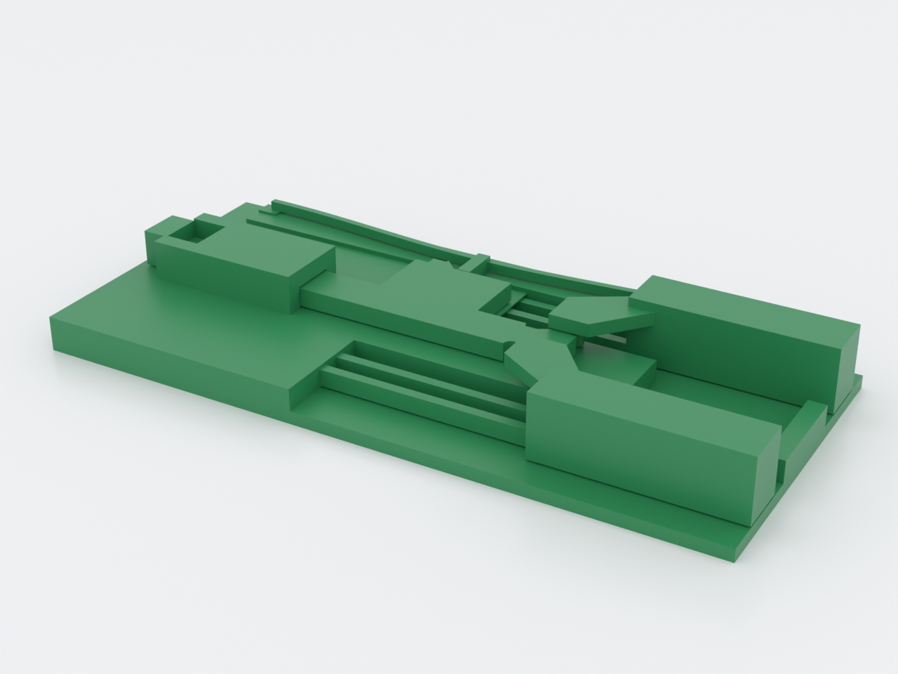

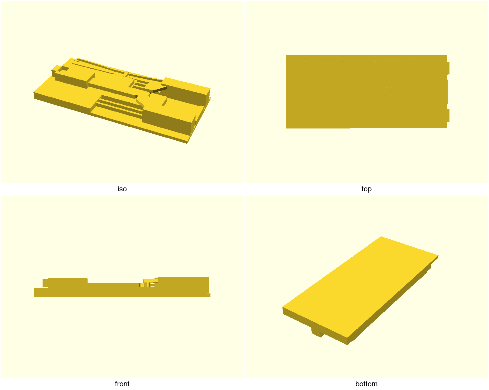
A print-in-place parallel-jaw gripper — one piece, off the bed assembled and
working. Push the tab and both jaws close in parallel (they stay mutually
parallel through the whole travel, so they clamp a cylinder on its full face,
not at two points); a bistable detent clicks in and holds the grip with zero
applied force. Pull the tab, the detent releases, and the leaf flexures spring
the jaws open. One of the "advanced" reference parts: it fuses all three domains
of docs/advanced-techniques.md in a single print.
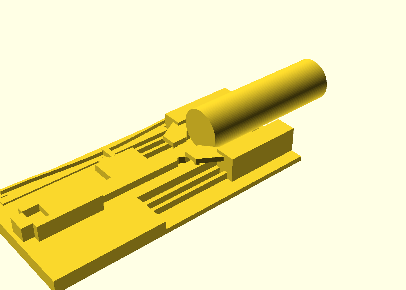
Loaded — a Ø 25 mm rod (the as-shipped grip size) lying in the trough between the jaws, tail overhanging the front edge. The rod is a preview prop, never part of the print:
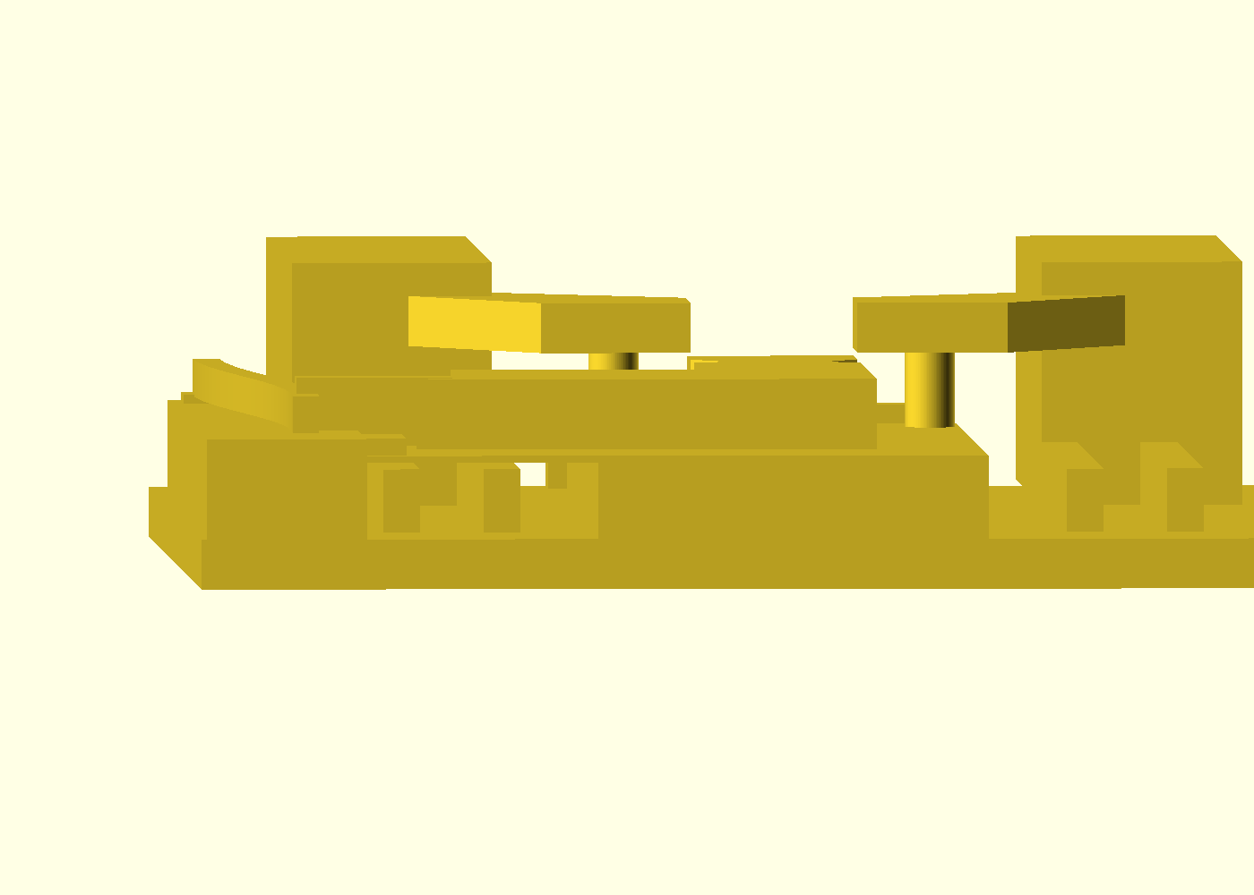
The same pose end-on down the trough: the rod's cross-section as a circle seated between the two pad faces, with the trough wall rising behind it. (The running daylight between rod and pads is the 3/4 view's job — see the shot above.)
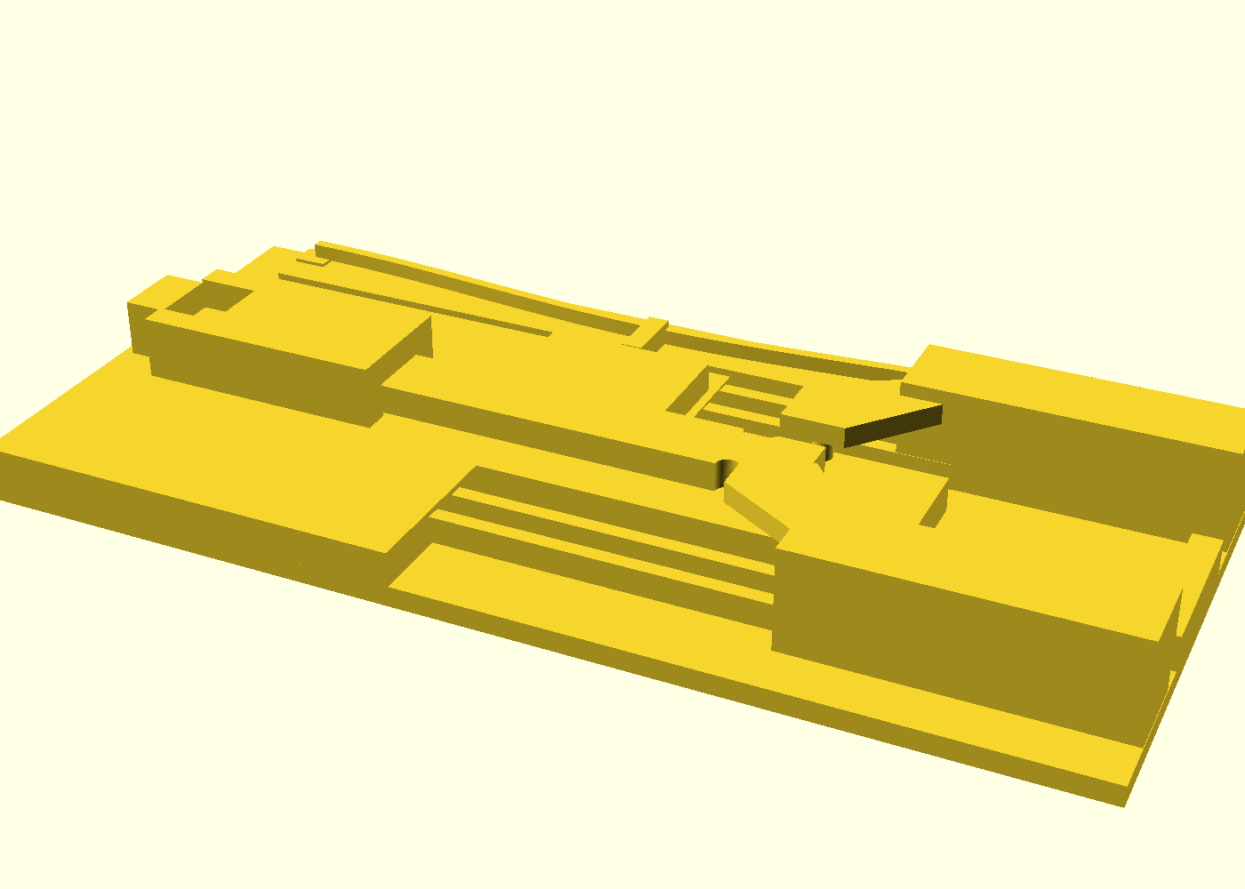
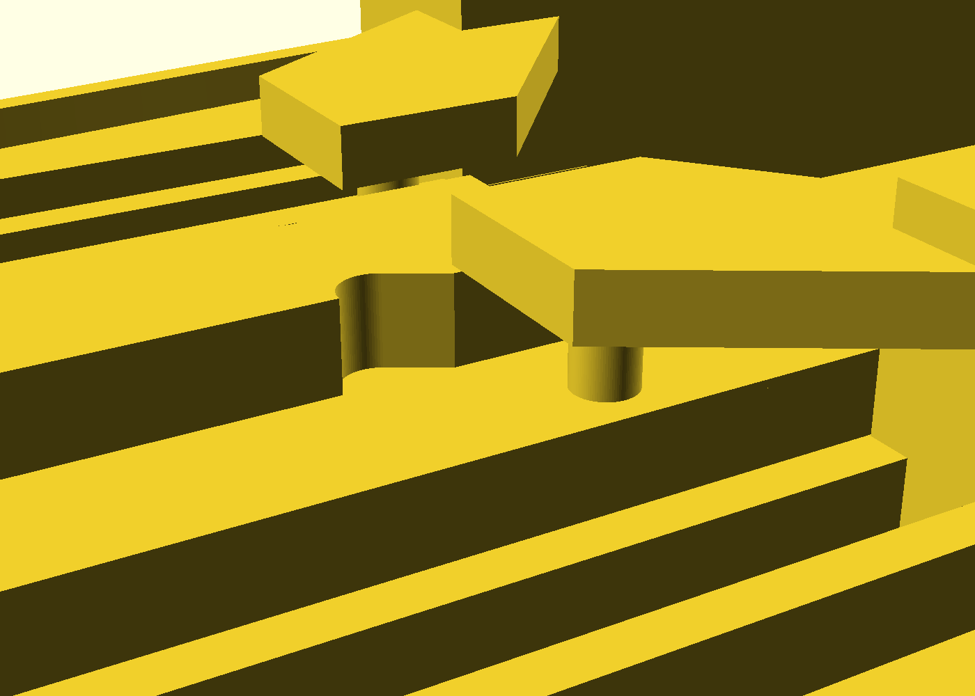
The cam that converts tab push into jaw closing (close-up) — the pin posts ride the diagonal notches cut into the plunger blade's edge:
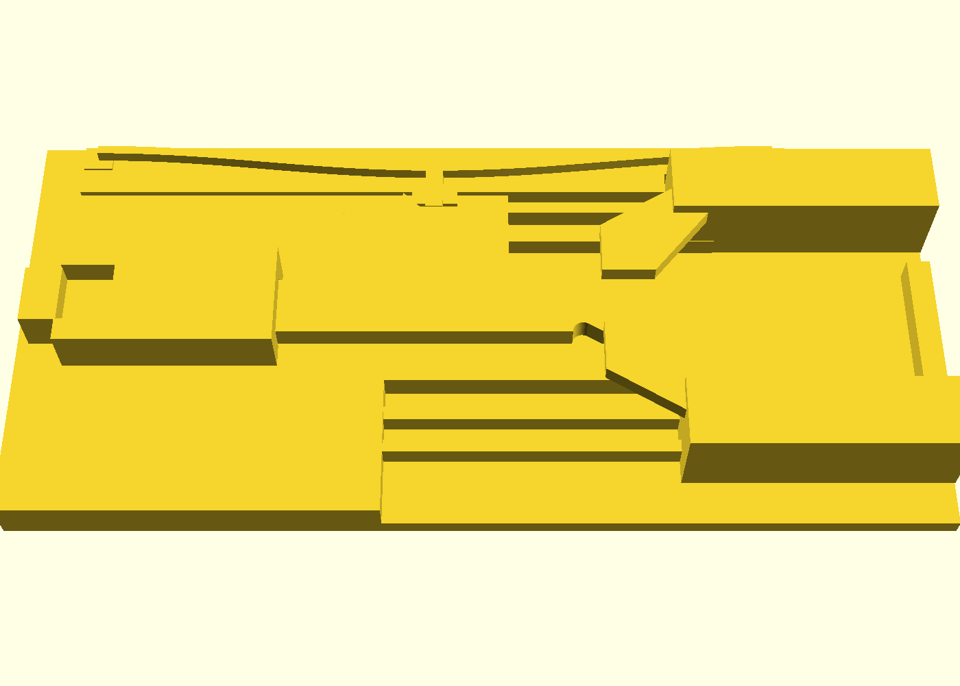
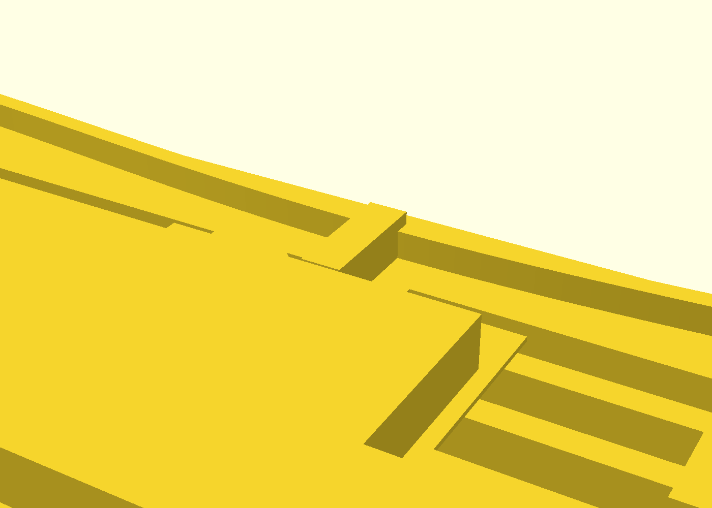
The bistable detent (close-up) — the pre-buckled arch's tip snaps over the crest into the valley on the plunger wing and holds the clamped state:
What you get
compliant-gripper— the part, 156 × 71 × 18 mm, printed flat in one piece. Grips a Ø 25 mm cylinder with 0.5 mm of preload per jaw (the pads close to a 24.0 mm gap); 8 mm of jaw travel; toggle force ≈ 3.8 N (a firm thumb push), held by the detent until you pull ≈ 5.7 N to release — both modeled figures, derived from the geometry; the field-test log owns the measured values.- The as-shipped working window is Ø 24–25.8 mm: under Ø 24 the pads seat
before they touch the rod, and the trough clears 25.8. A 1″ (25.4 mm) dowel
fits — at nominal 25.4: the window is narrower than the variance of the
stock it names (retail dowels run ±0.5 mm), so measure your stock, not
the label. A Ø 20 dowel grips air; a US quarter (Ø 24.26 mm) seats in the
window — a free desk demo. For other stock, re-derive from
grip_od— the parameter table below is the recipe. - It is a positioner, not a vise: at the seat each pad presses with the leaf preload — about 0.4 N, roughly 40 g of squeeze. That registers a rod in the trough while you file, sand or glue, and holds that state hands-free; it will not resist bearing down on the work — nor torque about the rod's own axis: a cylinder in side pads spins under the first crosswise file stroke, so work along the axis or expect to steady the rod. Locate and hold, don't clamp.
compliant-gripper-coupon— the print-this-first coupon: the same mechanism with the grip zone shortened. Honest price tag: it costs nearly as much as the part itself (~4 h 11 m vs 4 h 37 m sliced), because the leaves must stay at production length to prove the detent force balance — what it buys is knowing the fit and the snap before the real print, not a cheaper print. If 0.2 mm print-in-place clearances are known-good on your printer, print the part first — the coupon is the tuning instrument for when a fit sticks.
Print settings
- Material: PETG (the leaf flexures and the detent arch are live springs; PLA works but tires)
- Layer height: 0.2 mm, 0.4 mm nozzle — the clearances are quantized to whole layers, so keep both
- Infill: 30–40 %
- Supports: none needed — and none wanted. If your slicer flags print stability or offers supports: expected on this shape — the roof gaps are the design, and a support inside the mechanism welds it shut.
- Slicer, set these two: gap-closing radius 0.1 mm (the stock 0.2 default merges gaps at or under 0.2 mm — exactly this part's sliding clearances) and seam position Back or scarf (an Aligned seam stacks a ridge somewhere on the blade's long sliding flanks). The two knob names are PrusaSlicer's — translate for your slicer.
- Cooling: keep part cooling up — PETG sags on bridges where PLA doesn't, and the part has three deliberate bridges (the race rail's underside, the wing table, the arch beam over its shelf — the longest span on the part); a saggy rail underside is what closes the plunger's roof gap. But don't raise the global part fan for the bridges — leave the stock overhang/bridge auto-cooling on; it cools the three bridges where they need it and keeps the flexures tough
- Plate: textured PEI prints it clean; brim only if the long corners lift
- Orientation: as modelled, flat on the bed — the whole mechanism is one XY profile extruded in Z; printing it any other way breaks the flexures' in-layer bending and hangs the moving parts over air
- First use: work the tab once through its full stroke to free the race, then push it again and feel the detent click. Grit or crunch on the first stroke → that's bridge drool in one of the roof gaps (you can't see them from outside the part — the crunch is the test). Check cooling first; still crunchy → z_layers=3 + base_t=9 per the ladder below. Open, the plunger floats on its clearances and may tick faintly when jostled; clamped, it is preload-quiet — the sound story, not a defect.
- The scoot: pushing the plunger is ~20× what the part's own weight resists (a 3.8 N thumb push vs ~59 g of PETG on the bench) — hold the frame, or butt the long edge against a bench stop.
- Storage: store it open. Clamped, the detent holds the PETG arch deflected 2.2 mm, and PETG creeps under sustained load — an overnight glue-up is the use case and is fine, but parking it clamped for weeks may cost hold force.
How it works
Each jaw rides a parallelogram of two leaf flexures, so it translates in Y without rotating — that is what keeps the grip faces parallel. A captive plunger runs down the middle; its blade carries diagonal edge-notches, and pin posts on the jaws ride in them, so one tab push converts into equal and opposite jaw travel (a 30° wall: ×1.73 grip force per unit tab force, still shallow enough to slide back on release). A pre-buckled arch along one edge carries the detent tooth: push the tab and its tip climbs the ramp, passes the crest, and drops into a valley whose floor holds the arch deflected — the seat presses the tip against an 80° hold face, which holds the jaws' 3.9 N spring-back with a 6.2 N wall (both modeled). Pull past it and everything springs open.
The fusion: leaf-flexure jaws + the bistable arch (compliant mechanisms) × captive plunger, pin arms and detent tip printed in place with the PIP clearance recipe (0.2 mm vertical walls, 0.4 mm = 2-layer roof gaps) × support-free flat printing (the flexures bend in-layer; every moving underside — and every fixed feature the frame carries over the pocket — floats exactly two layers over a solid floor, shelf or table). The cross-section at the detent station shows the whole z-stack in one frame:
Committed fit-checks (ci.fitchecks) prove the plunger is a free captive body
and that the cam mouth actually opens through the blade — and a fuse-check
(ci.fusecheck) proves nothing welds shut.
Parameters
| Parameter | Default | What it does |
|---|---|---|
grip_od | 25 mm | what it grips — the pads preload this Ø by 0.5 mm per jaw |
jaw_travel | 8 mm | how far each jaw moves in Y (total gap closure 2×) |
preload | 0.5 mm | grip interference at the clamped seat (the grip force) |
ramp_ang | 30° | cam wall angle — force ratio vs self-return |
xy_tol | 0.2 mm | wall-to-wall clearance of every captive sliding pair |
z_layers | 2 | roof gaps, in whole 0.2 mm layers (0.4 mm) |
leg_l / leg_z | 55 / 3.8 mm | leaf flexure length/thickness — the jaw spring rate |
arch_rise / arch_t | 3.8 / 1.6 mm | the detent arch's rise and thickness — the toggle force |
seat_u / hold_ang | 2.2 mm / 80° | detent valley depth and hold-face angle — the holding margin |
All parameters are at the top of compliant-gripper.scad, grouped in Customizer
sections; override on the command line with -D 'grip_od=30'. If you change the
grip size, the stroke and detent placement re-derive automatically — but keep
the detent's hold margin (the guards in the file refuse a set that loses it).
If a fit is off
Print the coupon first. Plunger fused at its sides → raise xy_tol by
0.05 and reprint; rattles → lower it the same. Plunger fused under the
rail → that is a Z problem, not XY (the roof gap closed — PETG bridge sag is
the usual culprit; check cooling first): raise z_layers to 3, and base_t
to 9 with it — the wing table lives in the band the bigger gap eats, and the
file's guard walks you through it — at the cost of 0.2 mm of captive height.
Solid tab, no click at all → the corridor roof gap under the arch welded
(the same Z problem as the rail — PETG bridge sag): raise z_layers to 3 and
base_t to 9, and try that before seat_u or thinner leaves. Detent won't
hold (but the tab still clicks) → do not steepen hold_ang; raise seat_u
(deeper preload) or thin the leaves — the file's guards will tell you which way
the force balance still closes.