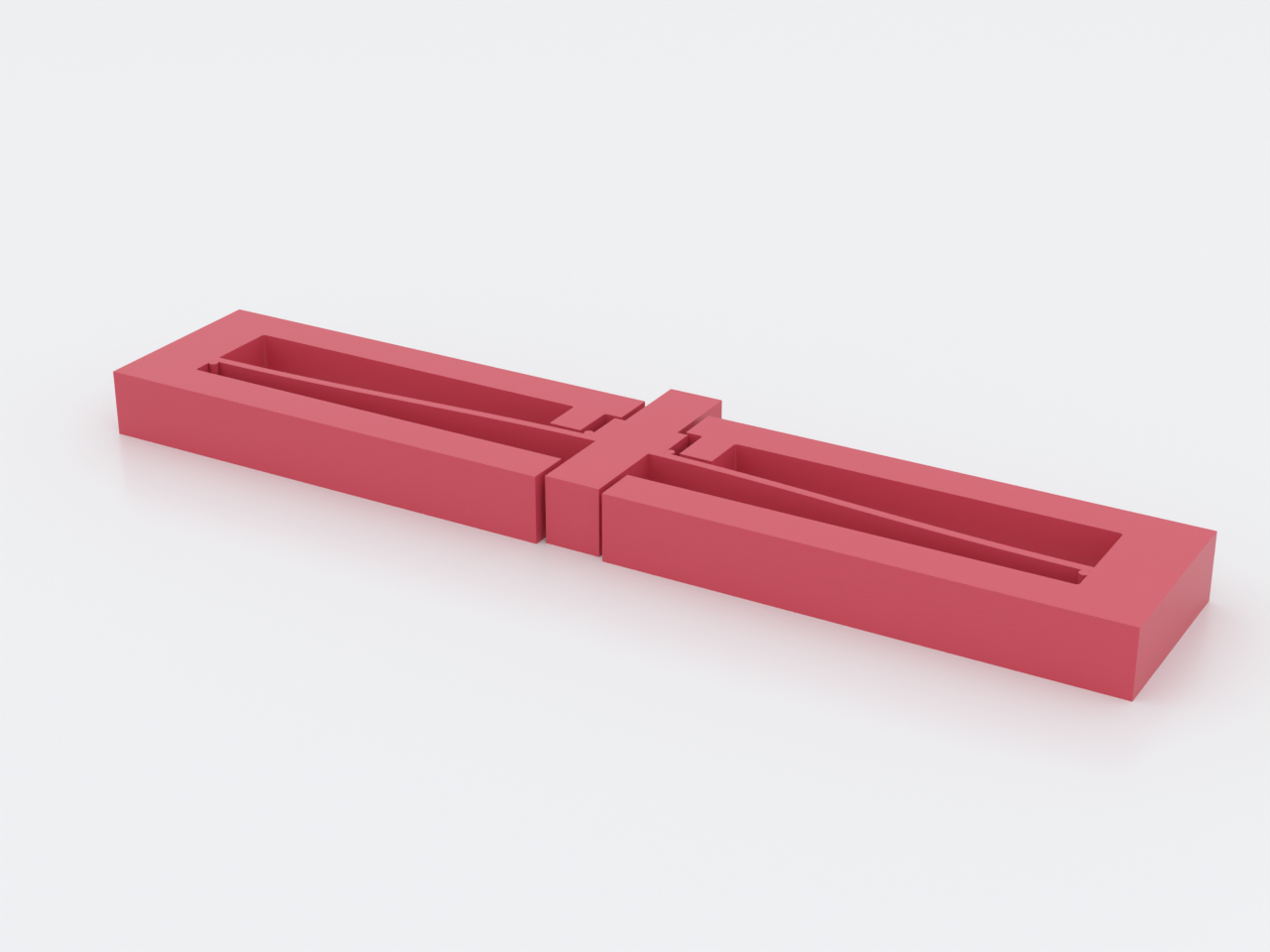
A monolithic bistable push switch: a pre-buckled arch with two stable states
(bowed up / bowed down) separated by a negative-stiffness region. Press the
proud push stem and the arch snaps through flat to the other state and stays
there — power is only needed to switch, never to hold. The stems are a mirrored
pair riding the arch centre through windows in the stop cage: whichever state
the toggle is in, exactly one stem stands proud of the cage, and pressing it is
the next switch — one motion of one finger, in both states. Dimensioned from
feel targets, not by eye: a 3 N fingertip snap with 4 mm of travel —
predictions solved back from published fixed–fixed-arch constants against a
textbook PETG modulus, for the coupon to verify on your printer, not
guarantees. A worked example of the bistable / constant-force family
(docs/advanced-techniques.md, Domain 1).
What you get
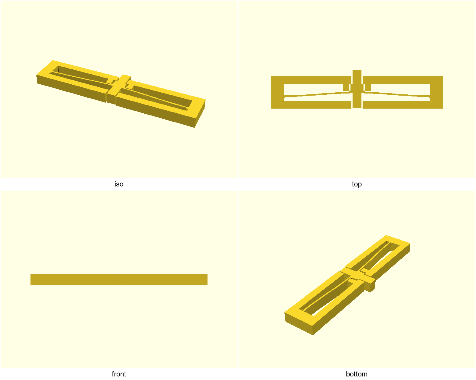
bistable-toggle— one flat part, ≈ 94 × 21 × 6 mm. The arch snaps inside a rigid stop cage (lid above, base bar below, rails flanking the nub) that absorbs over-travel and sideways shoves, so the flexure only ever feels the motion it was solved for. The lid and base bar are windowed over the push stems, and the over-travel stops sit outside the push column: the +Y stop is the nub's shoulders catching the lid-window jambs at the same 0.4 mm gap, and the −Y stop is the arch meeting the base-bar jambs beside its window (first contact ≈ 0.43 mm at the window edge — the 0.4 design gap plus the arch's curvature drop across the half-window). Use it as a latch, a damper hold, or a tactile toggle that holds state with zero power.bistable-toggle-coupon— print this first: a 4-cell strip sweeping the bistability threshold on your printer (below).
How to press it: the push is in the part's plane. Lying flat on the table the stems point along the table, not at the ceiling — press the proud stem straight in, like a doorbell set into the frame's edge, until the snap carries it through; then the opposite stem stands proud for the return press. (Pressing the part's broad top face does nothing: that is the ~50× stiffer out-of-plane axis, and no push face lives there.)
Fixing & which way up: there are no fastener holes by design — the frame is the ground, so fix the part by its end-post faces only. Never bond the base bar's or lid's outer face flush: the hidden stem crosses that plane by 3.5 mm on every snap, so glue or tape there sits innocently flush and bricks the switch on the first press (if you must mount by that face, relieve ≥ 3.5 mm behind the window zone). A printed pocket should grip the end posts — a full-length slot on the 6 mm frame clamps the arch and stems solid, since everything on this part is the same 6 mm thick. Loose on a desk, the 6 g part skates under its own 3 N button — pinch the end posts or fix it first. Either face may be "up": the mechanism is symmetric through its plane — mount it so the stem you'll press most often faces the operator.
Print settings
- Material: PETG — the easy path, and the only one the solve's
E = 2000 MPadatum actually describes. PP and nylon flex just as well but are traps on stock hardware: PP barely adheres to PEI (strap the plate with packing tape), and un-dried nylon loses layer adhesion exactly where the beam lives (dry box + enclosure). Not PLA — the second state holds a small residual stress in a live flexure, and PLA creeps under sustained load: a PLA toggle stops clicking within months and just sits there half-snapped. - Layer height: 0.2 mm
- Infill: 100 % / high perimeters
- Supports: none — everything, the stop cage included, is pure profile and prints flat face-down. Keep auto-supports off; the mechanism needs none and painted ones would weld it.
- Orientation: flat, as modelled — the arch snaps in the layer plane, so bending stress runs across roads within a layer, not between them
- Plate: textured PEI if you have it — PETG over-welds on smooth, and the moving clearances touch the bed (next line)
- First layer: set Elephant foot compensation: 0.2 mm — stock profiles ship it at 0.0, so "enabled" isn't a state the machine has, a number is. Every moving clearance here is a layer-1 clearance: the 0.4 mm stop gaps at the nub, the rail faces and the 0.6 mm stem↔window slots all run the full height including layer 1, where squish can pinch the thinnest to a hairline web. Expect a gritty first press: it shears the layer-1 tack webs and the PETG wisps strung across every through-height gap — the stem windows, the rail gaps, the stop gaps — normal, not damage. The through-cut windows give the debris somewhere to go, so the second press should feel clean; only if it doesn't is there anything to tune (each coupon cell has the same slots, so the strip shows you the feel first)
- Seam: Back (cosmetic — nothing mates on a perimeter)
The 0.82 mm arch beam prints as two clean perimeters at a 0.4 mm nozzle. If the first snap feels dead or the "2.5" coupon cell only springs back, your material landed outside the solve — calibrate with the coupon before blaming the part.
How it's dimensioned
Pick the feel you want, the geometry follows: h = u_tr/1.98 and
l = (1486.57·E·I·h/f_s)^(1/3) with I = w·t³/12. The defaults invert to
f_s ≈ 3 N, u_tr ≈ 4 mm (echoed at render, asserted against the targets).
Bistability requires mid_rise/beam_t ≳ 2.3 — below that it's just a spring,
and the design refuses to build it. The full solve chain is in NOTES.md.
Parameters
| Parameter | Default | What it does |
|---|---|---|
target_fs | 3 N | target switch force — the solve derives span from it |
target_utr | 4 mm | target centre travel — the solve derives mid_rise from it |
E | 2000 MPa | Young's modulus (PETG datum) — scale to your measured snap |
mid_rise | 2.02 mm | arch rise h (derived from target_utr) |
beam_t | 0.82 mm | arch thickness t — window [0.8, 0.878]: 0.8 is the two-perimeter floor, 0.878 the bistability cap |
span | ≈ 82 mm | clamped span l (derived from target_fs) |
width | 6 mm | out-of-plane width = print height |
stop_gap | 0.4 mm | travel past a stable state before a hard stop bites |
stem | [5, 3.5] mm | push stem [width, proud height]; proud must exceed the rise h or the finger bottoms on the cage before snap-through (asserted) |
stem_clear | 0.6 mm | stem↔window clearance — kept above stop_gap so the ±X rails always bite before a stem touches its jamb |
Bistability holds while mid_rise/beam_t ≥ 2.3. All parameters are at the top of
bistable-toggle.scad; override with -D 'target_fs=2.5' and the derived
dimensions follow.
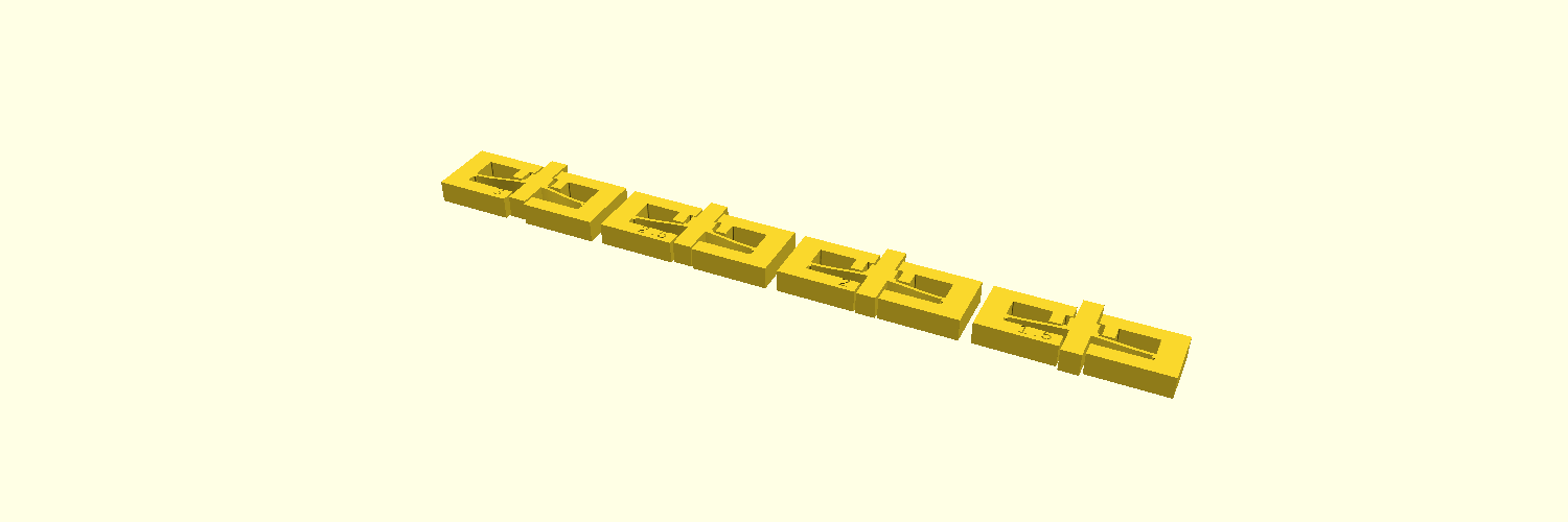
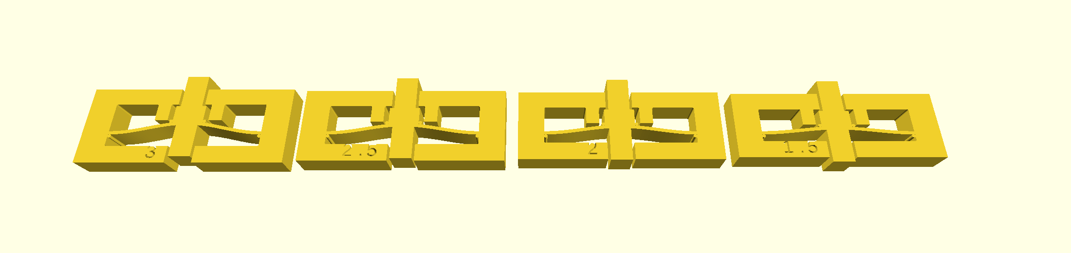
Print this first: the coupon
bistable-toggle-coupon.scad prints four small cells labelled 3 / 2.5 / 2 /
1.5 — their mid_rise/beam_t ratios at the production thickness. Left to
right: bistable, bistable (the production ratio), monostable, monostable. Four
cells because this is a family calibration with negative controls, not a copy
of the part: two cells are deliberately dead so you know the test can fail.
Press each cell's proud stem — every cell carries the same stems and windows as
the production part, so the strip teaches the same motion. Feel the snap die
between 2.5 and 2 — that is your printer landing where the solve assumed. If
2.5 only springs back for you, raise mid_rise; if the production snap is too
fierce, lower it. Steps in NOTES.md → "Print this first".
Two expectations, so the strip reads right: the cells are short (l = 35 vs
the part's 82) and switch force scales as 3 N), and hold the strip down while you press. Expect roughly
4 kg on the two live cells — press with the ball of your thumb, strip flat on
the bench. And the strip
is the bigger commitment on purpose: about 1 h 26 m / 15 g of insurance
against the toggle's ~32 m / 6.3 g — the honest first evening is both on
one plate. The strip is ~197 mm long: on beds under ~210 mm, print it rotated
45° or two cells at a time — and if you add a brim for adhesion it will bridge
the 3 mm gaps and print the strip as one piece (harmless to the calibration;
just break the cells apart at the web before pressing).1/l³, so they snap roughly 13×
harder than the part — feel for whether each state holds, not for the
production force (